#!/usr/bin/env python
# -*- coding: utf-8 -*-

import rospy
import numpy as np
import cv2, random, math, time

Width = 640
Height = 480
Offset = 420
Gap = 40

# draw lines
def draw_lines(img, lines):
    global Offset
    for line in lines:
        x1, y1, x2, y2 = line[0]
        color = (random.randint(0, 255), random.randint(0, 255), random.randint(0, 255))
        img = cv2.line(img, (x1, y1+Offset), (x2, y2+Offset), color, 2)
    return img

# draw rectangle
def draw_rectangle(img, lpos, rpos, offset=0):
    center = (lpos + rpos) / 2

    cv2.rectangle(img, (lpos - 5, 15 + offset),
                       (lpos + 5, 25 + offset),
                       (0, 255, 0), 2)
    cv2.rectangle(img, (rpos - 5, 15 + offset),
                       (rpos + 5, 25 + offset),
                       (0, 255, 0), 2)
    cv2.rectangle(img, (center-5, 15 + offset),
                       (center+5, 25 + offset),
                       (0, 255, 0), 2)
    cv2.rectangle(img, (315, 15 + offset),
                       (325, 25 + offset),
                       (0, 0, 255), 2)
    return img

# left lines, right lines
def divide_left_right(lines):
    global Width

    low_slope_threshold = 0
    high_slope_threshold = 10

    # calculate slope & filtering with threshold
    slopes = []
    new_lines = []

    for line in lines:
        x1, y1, x2, y2 = line[0]

        if x2 - x1 == 0:
            slope = 0
        else:
            slope = float(y2-y1) / float(x2-x1)

        if abs(slope) > low_slope_threshold and abs(slope) < high_slope_threshold:
            slopes.append(slope)
            new_lines.append(line[0])

    # divide lines left to right
    left_lines = []
    right_lines = []

    for j in range(len(slopes)):
        Line = new_lines[j]
        slope = slopes[j]

        x1, y1, x2, y2 = Line

        if (slope < 0) and (x2 < Width/2 - 90):
            left_lines.append([Line.tolist()])
        elif (slope > 0) and (x1 > Width/2 + 90):
            right_lines.append([Line.tolist()])

    return left_lines, right_lines

# get average m, b of lines
def get_line_params(lines):
    # sum of x, y, m
    x_sum = 0.0
    y_sum = 0.0
    m_sum = 0.0

    size = len(lines)
    if size == 0:
        return 0, 0

    for line in lines:
        x1, y1, x2, y2 = line[0]

        x_sum += x1 + x2
        y_sum += y1 + y2
        m_sum += float(y2 - y1) / float(x2 - x1)

    x_avg = float(x_sum) / float(size * 2)
    y_avg = float(y_sum) / float(size * 2)

    m = m_sum / size
    b = y_avg - m * x_avg

    return m, b

# get lpos, rpos
def get_line_pos(lines, left=False, right=False):
    global Width, Height
    global Offset, Gap

    m, b = get_line_params(lines)

    x1, x2 = 0, 0
    if m == 0 and b == 0:
        if left:
            pos = 0
        if right:
            pos = Width
    else:
        y = Gap / 2
        pos = (y - b) / m

        b += Offset
        x1 = (Height - b) / float(m)
        x2 = ((Height/2) - b) / float(m)

    return x1, x2, int(pos)

# show image and return lpos, rpos
def process_image(frame):
    global Width
    global Offset, Gap

    # gray
    gray = cv2.cvtColor(frame,cv2.COLOR_BGR2GRAY)

    # blur
    kernel_size = 5
    blur_gray = cv2.GaussianBlur(gray,(kernel_size, kernel_size), 0)

    # canny edge
    low_threshold = 60
    high_threshold = 70
    edge_img = cv2.Canny(np.uint8(blur_gray), low_threshold, high_threshold)

    # HoughLinesP
    roi = edge_img[Offset : Offset+Gap, 0 : Width]
    all_lines = cv2.HoughLinesP(roi,1,math.pi/180,30,30,10)

    # divide left, right lines
    if all_lines is None:
        return (0, 640), frame

    left_lines, right_lines = divide_left_right(all_lines)

    # get center of lines
    lx1, lx2, lpos = get_line_pos(left_lines, left=True)
    rx1, rx2, rpos = get_line_pos(right_lines, right=True)

    frame = cv2.line(frame, (int(lx1), Height), (int(lx2), (Height/2)), (255, 0,0), 3)
    frame = cv2.line(frame, (int(rx1), Height), (int(rx2), (Height/2)), (255, 0,0), 3)

    # draw lines
    frame = draw_lines(frame, left_lines)
    frame = draw_lines(frame, right_lines)
    frame = cv2.line(frame, (230, 235), (410, 235), (255,255,255), 2)

    # draw rectangle
    frame = draw_rectangle(frame, lpos, rpos, offset=Offset)

    return (lpos, rpos), frame

def draw_steer(image, steer_angle):
    global Width, Height, arrow_pic

    arrow_pic = cv2.imread('steer_arrow.png', cv2.IMREAD_COLOR)

    origin_Height = arrow_pic.shape[0]
    origin_Width = arrow_pic.shape[1]
    steer_wheel_center = origin_Height * 0.74
    arrow_Height = Height/2
    arrow_Width = (arrow_Height * 462)/728

    matrix = cv2.getRotationMatrix2D((origin_Width/2, steer_wheel_center), (steer_angle) * 2.5, 0.7)
    arrow_pic = cv2.warpAffine(arrow_pic, matrix, (origin_Width+60, origin_Height))
    arrow_pic = cv2.resize(arrow_pic, dsize=(arrow_Width, arrow_Height), interpolation=cv2.INTER_AREA)

    gray_arrow = cv2.cvtColor(arrow_pic, cv2.COLOR_BGR2GRAY)
    _, mask = cv2.threshold(gray_arrow, 1, 255, cv2.THRESH_BINARY_INV)

    arrow_roi = image[arrow_Height: Height, (Width/2 - arrow_Width/2) : (Width/2 + arrow_Width/2)]
    arrow_roi = cv2.add(arrow_pic, arrow_roi, mask=mask)
    res = cv2.add(arrow_roi, arrow_pic)
    image[(Height - arrow_Height): Height, (Width/2 - arrow_Width/2): (Width/2 + arrow_Width/2)] = res

    cv2.imshow('steer', image)

def start():

    global image, Width, Height

    cap = cv2.VideoCapture('hough_track.avi')

    while not rospy.is_shutdown():

        ret, image = cap.read()
        time.sleep(0.03)

        pos, frame = process_image(image)

        center = (pos[0] + pos[1]) / 2
        angle = 320 - center

        steer_angle = angle * 0.4
        draw_steer(frame, steer_angle)

        if cv2.waitKey(1) & 0xFF == ord('q'):
            break

if __name__ == '__main__':
    start()
draw_lines == img 는 640 * 480 으로 주어지고 lines는 divide_left_right 함수를 통해 찾은 왼쪽, 오른쪽 선분들의 모음이다.
선분의 시작점과 끝점을 얻은후에 랜덤으로 얻은 색으로 선을 그어준다. 영상에서 양쪽끝에 여러 색깔로 짧은(관심영역안의) 선분들을 확인을 할 수 있다.
draw_rectangle == lpos, rpos는 왼쪽 오른쪽 차선의 x좌표 값이다. 그것을 기준으로 사각형을 그리는 것이다. 또한 방향조정을 참조하기위한 가운데에 빨간 사각형을 그려준다.
divide_left_right == lines 는 허프만 함수를 통해 찾은 선분들의 모음이다. slope = 0 인경우는 수직선의 경우이다.
선분의 기울기의 최대값과 최소값을 주어주는데 이유는 원근법 때문에 카메라에서는 선분이 ,즉 차선이 일직선으로 보이지않고 약간 기울어져있기 때문이다.
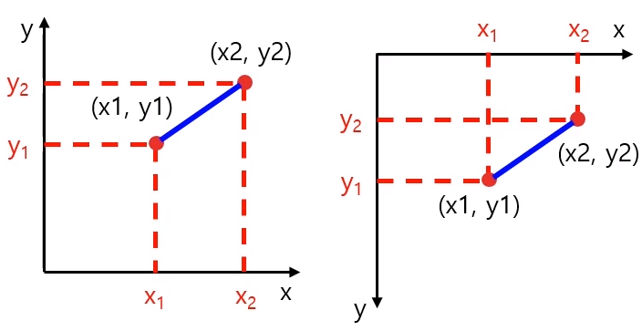
opencv 에서는 좌표계가 오른쪽과 같다. 그러므로 left_lines, right_lines에 넣어주는 기준을 조금 다르게 고려해주어야한다.
get_line_params == lines 들어오는 인자는 left_lines, 이거나 right_lines가 들어온다. 여기서 하는것은 많은 선분들을 평균을 하여 하나의 선분으로 변환 시켜준다.
get_line_pos == m,b 가 각각 0 일때는 선분을 못찾았을 때임으로 그냥 화면의 맨끝에 차선이 있다고 가정한다.
y = Gap / 2 로 한후 pos를 구하는 이유는 추후에 사각형을 그려줄때 가운데 그리기 위함이다.
b+= Offset 은 아래쪽 큰 직사각형을 0,0으로 생각하고 호프만 함수를 통해 선분을 구했음으로 전체좌표계로 되돌리면 y축으로 평행이동 시켜주면 되는 것이다.
x1,x2 는 평행이동한 선분을 쭈욱 늘려서 그려주기 위한 작업이다.
draw_steer == steer_angle 값에 따라서 steer_arrow.png , arrow.png 를 회전 시켜서 그려주는 코드이다.
Translation 평행이동
import cv2
import numpy as np

img = cv2.imread('girl.png')
rows,cols = img.shape[0:2]
dx, dy = 100, 50

mtrx = np.float32([[1, 0, dx],
                   [0, 1, dy]])

dst = cv2.warpAffine(img, mtrx, (cols+dx, rows+dy))


dst2 = cv2.warpAffine(img, mtrx, (cols+dx, rows+dy), None, \
                        cv2.INTER_LINEAR, cv2.BORDER_CONSTANT, (255,0,0) )

dst3 = cv2.warpAffine(img, mtrx, (cols+dx, rows+dy), None, \
                                cv2.INTER_LINEAR, cv2.BORDER_REFLECT)

cv2.imshow('original', img)
cv2.imshow('trans', dst)
cv2.imshow('BORDER_CONSTATNT', dst2)
cv2.imshow('BORDER_REFLECT', dst3)
cv2.waitKey(0)
cv2.destroyAllWindows()

2x3 matrix를 통해 사진을 x축으로 100 y축으로 50만큼 평행이동 시켰다. BORDER_REFLECT를 보면 왼쪽의 검은색으로 남는 부분이 거울처럼 반사된 사진들로 채워진것을 확인 할 수 있다.
Scaling 확대축소
import cv2
import numpy as np

img = cv2.imread('girl.png')
height, width = img.shape[0:2]

m_small = np.float32([[0.5, 0, 0],
                      [0, 0.5, 0]])

m_big = np.float32([[2, 0, 0],
                    [0, 2, 0]])


dst1 = cv2.warpAffine(img, m_small, (int(height*0.5), int(width*0.5)))


dst2 = cv2.warpAffine(img, m_small, (int(height*0.5), int(width*0.5)), \
                        None, cv2.INTER_AREA)

dst3 = cv2.warpAffine(img, m_big, (int(height*2), int(width*2)))

dst4 = cv2.warpAffine(img, m_big ,(int(height*2) ,int(width*2)),None,cv2.INTER_CUBIC)

cv2.imshow("original", img)
cv2.imshow("small", dst1)

cv2.imshow("small INTER_AREA", dst2)
cv2.imshow("big",dst3)
cv2.imshow("big INTER_CUBIC",dst4)
cv2.waitKey(0)
cv2.destroyAllWindows()
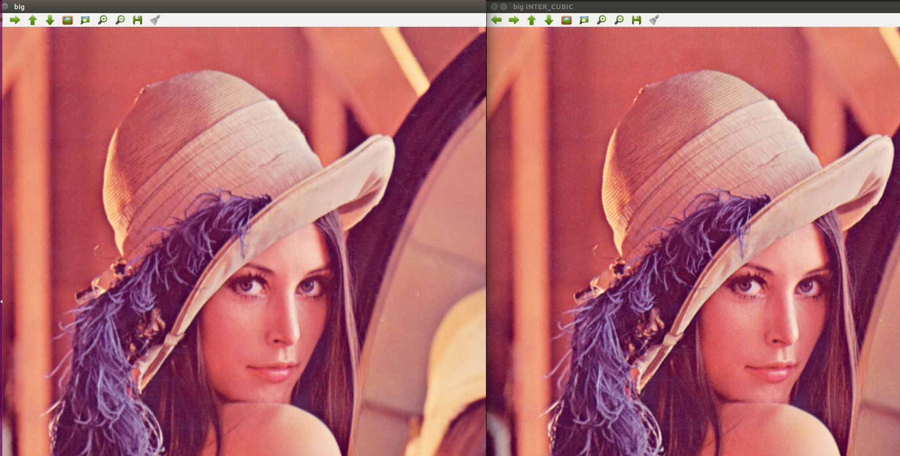
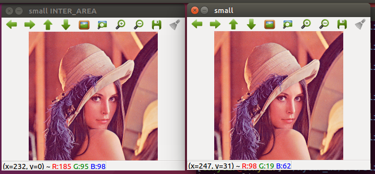
축소할때는 Inter_area 확대할떄는 inter_cubic을 쓰는게 원본이미자와 유사하게 스케일링을 할 수 있다.
dst1 = cv2.resize(img, (int(width*0.5), int(height*0.5)), \
                         interpolation=cv2.INTER_AREA)

dst2 = cv2.resize(img, None,  None, 0.5, 1.5, cv2.INTER_CUBIC)
resize 함수를 통해서도 크기를 변경할 수 있다.
Rotation 회전
import cv2
import numpy as np

img = cv2.imread('girl.png')

rows,cols = img.shape[0:2]

d45 = 45.0 * np.pi / 180
d90 = 90.0 * np.pi / 180


m45 = np.float32( [[ np.cos(d45), -1* np.sin(d45), rows//2],
                    [np.sin(d45), np.cos(d45), -1*cols//4]])

m90 = np.float32( [[ np.cos(d90), -1* np.sin(d90), rows],
                    [np.sin(d90), np.cos(d90), 0]])


r45 = cv2.warpAffine(img,m45,(cols,rows))
r90 = cv2.warpAffine(img,m90,(cols,rows))


cv2.imshow("origin", img)
cv2.imshow("45", r45)
cv2.imshow("90", r90)
cv2.waitKey(0)
cv2.destroyAllWindows()
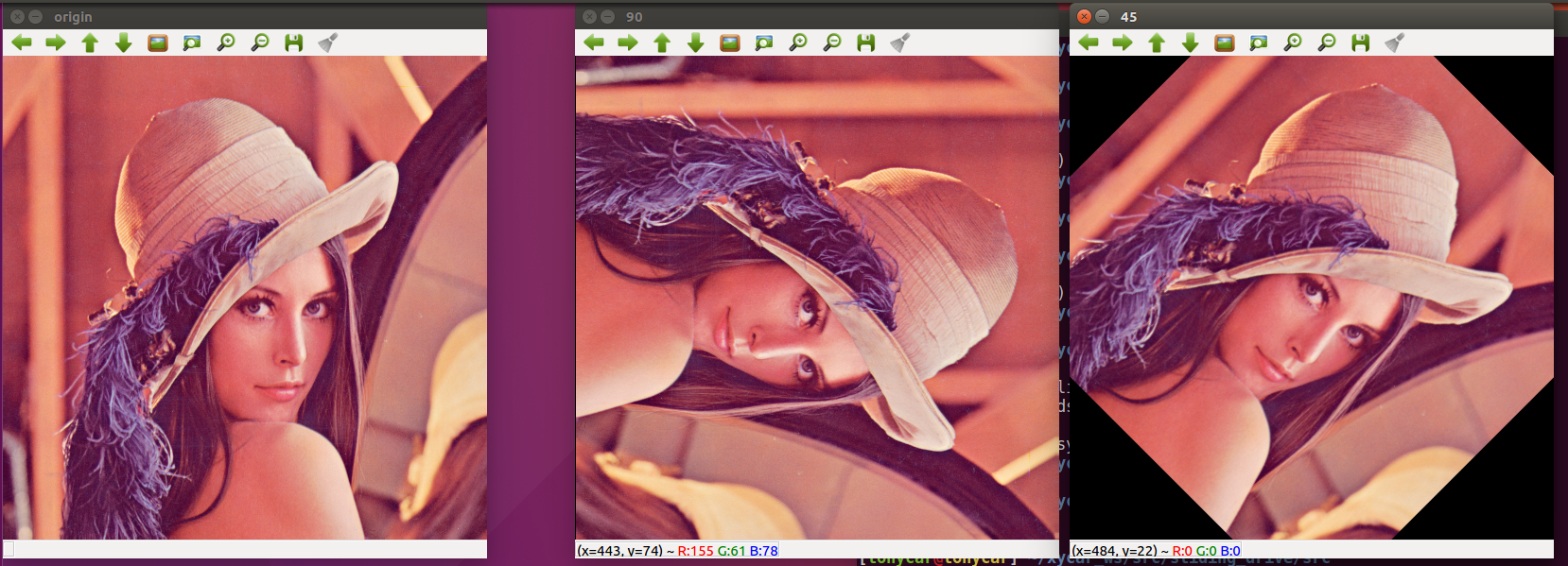
기준점이 좌측 최상단(원점) 이기때문에 시계방향으로 회전을하면 화면 바깥으로 나가게 된다. 회전행렬을 만들때 평행이동도 고려를 해주어야 한다.
아래와 같이 getRotationMatrix2D(center,angle,scale)을 통해서 간단하게 회전시킬 수 있다.
m45 = cv2.getRotationMatrix2D((cols/2,rows/2),45,0.5)
Affine 아핀변환 == 크기변환, 이동변환, 회전변환에서 도 원래 평행했던 특성을 그대로 유지
import cv2
import numpy as np
from matplotlib import pyplot as plt

img = cv2.imread('chess.png')

rows,cols = img.shape[0:2]


pts1 = np.float32([[50,50],[200,50],[50,200]])

pts2 = np.float32([[10,100],[200,50],[100,250]])

M = cv2.getAffineTransform(pts1,pts2)
print M

dst = cv2.warpAffine(img,M,(cols,rows))

plt.subplot(121),plt.imshow(img),plt.title('Input')
plt.subplot(122),plt.imshow(dst),plt.title('Output')
plt.show()
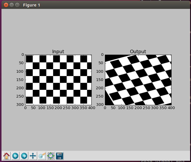
3 가지 점을 기준으로 변환을 시켜준다. getAffineTransform 을 통해 변환행렬을 얻는다. 그 변환행렬을 warpAffine 함수에게 넣어준다.
Perspective 원근 변환
import cv2
import numpy as np
from matplotlib import pyplot as plt

img = cv2.imread('chess.png')

rows,cols = img.shape[0:2]

pts1 = np.float32([[20,20],[20,280],[380,20],[380,280]])

pts2 = np.float32([[100,20],[20,280],[300,20],[380,280]])

cv2.circle(img, (20,20), 20, (255,0,0),-1)
cv2.circle(img, (20,280), 20, (0,255,0),-1)
cv2.circle(img, (380,20), 20, (0,0,255),-1)
cv2.circle(img, (380,280), 20, (0,255,255),-1)

M = cv2.getPerspectiveTransform(pts1, pts2)
print M

dst = cv2.warpPerspective(img, M, (cols,rows))

plt.subplot(121),plt.imshow(img),plt.title('image')
plt.subplot(122),plt.imshow(dst),plt.title('Perspective')
plt.show()
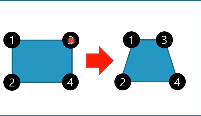
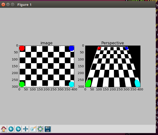
역으로도 가능하다. 위와 비슷하게 이번에는 4개의 점을 통해 변환행렬을 만들고 그것을 warpPerspective 함수에 넣어준다.
'자율주행 > ROS python (xytron 강의)' 카테고리의 다른 글
| 슬라이딩 윈도우 기반 차선인식 (0) | 2021.01.26 |
|---|---|
| line_find.py 주어진 영상에서 차선 찾기 (0) | 2021.01.22 |
| Rosbag file을 통해 비디오생성 (0) | 2021.01.19 |
| Opencv tutorial_1 (0) | 2021.01.18 |
| 8자 주행 ,ultrasonic 내 코드 정리 (0) | 2021.01.14 |